

Apa Saja Game Slot Gacor yang Wajib Dipilih?
Slot sudah hadir dengan sistem online. Hal ini menjadi kabar gembira bagi para pecinta judi slot karena itu membawakan kemudahan yang luar biasa. Kalau tidak ada akses slot online ini, judi slot masih harus dimainkan di tempat judi tertentu yang sama sekali tidak praktis. Slot gacor online menjadikan judi slot sangat gampang karena semuanya hanya […]

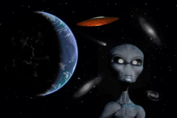
Apakah Alien Memang Benar-Benar Ada?
Apakah Alien Memang Benar-Benar Ada? – Keberadaan Alien pada saat ini merupakan salah satu hal yang cukup menarik untuk diperbincangkan mengingat teknologi dan akses luar angkasa juga semakin banyak ditemukan. Sebagian orang menganggap bahwa alien merupakan makhluk yang menakutkan atau berbahaya bagi kehidupan manusia, namun di lain sisi terdapat juga sebagian orang yang justru menganggap […]

Mengapa Kita Ingin Menemukan Alien?
Mengapa Kita Ingin Menemukan Alien? – Saat ini, kita memiliki teleskop dan pesawat ruang angkasa yang jauh lebih unggul yang dapat menjelajahi dunia lain dari dekat. Kita tahu lebih banyak tentang komposisi tata surya kita, sampai ke lautan metana dingin yang aneh di bulan Saturnus, Titan, dan detail permukaan berbintik-bintik coklat dan merah dari bulan […]

Penelitian Tentang Bima Sakti Memiliki 4 Peradaban Alien
Penelitian Tentang Bima Sakti Memiliki 4 Peradaban Alien – Peneliti menunjukkan dengan tepat sumber “Sinyal WoW”, yang terdeteksi pada tahun 1977 dan merupakan ledakan energi radio yang aneh selama satu menit. Penelitian Tentang Bima Sakti Memiliki 4 Peradaban Alien alienscalpel – Ada kira-kira empat peradaban luar angkasa berbahaya di Bima Sakti yang dapat menyerang planet […]
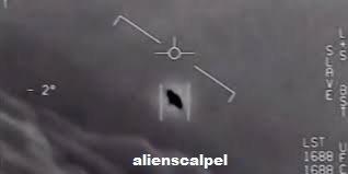
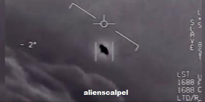
Ada Apa di Dalam Laporan UFO Yang Sudah Lama Ditunggu-Tunggu Pentagon
Ada Apa di Dalam Laporan UFO Yang Sudah Lama Ditunggu-Tunggu Pentagon – Salah satu dari banyak keingintahuan yang dimasukkan ke dalam pengeluaran omnibus senilai $2,3 triliun dan paket bantuan virus corona yang disahkan oleh Kongres pada bulan Desember adalah ketentuan yang mewajibkan Departemen Pertahanan dan Kantor Direktur Intelijen Nasional untuk mengirimkan laporan yang tidak terklasifikasi […]

5 Dokumenter UFO Yang Menjawab Pertanyaan Tentang Kehidupan Alien
5 Dokumenter UFO Yang Menjawab Pertanyaan Tentang Kehidupan Alien – Apa yang Anda bayangkan ketika memikirkan kehidupan di luar bumi? (2016) brilian dan berbakat. Apakah ET cantik dari film Steven Spielberg Heptapods in Arrival (1982) atau monster berdarah dingin yang menginvasi bumi dengan mutasi misterius dalam Annihilation (2018)? Selama kita hidup, orang bertanya-tanya apakah kita […]

Apakah Alien Menemukan Kita?
Apakah Alien Menemukan Kita? – Itu adalah objek antarbintang pertama yang terdeteksi di tata surya kita; para ilmuwan menamainya ‘Oumuamua, kata Hawaii untuk pramuka atau pembawa pesan. Oktober berikutnya, Avi Loeb, ketua departemen astronomi Harvard, ikut menulis sebuah makalah (dengan rekan postdoctoral Harvard, Shmuel Bialy) yang meneliti “percepatan aneh” ‘Oumuamua’ dan menyarankan bahwa objek tersebut […]
UFO: Mengapa Pemerintah Tidak Mengungkapkan Informasi Tentang Alien
UFO: Mengapa Pemerintah Tidak Mengungkapkan Informasi Tentang Alien – Apakah seseorang akan membuktikan Fox Mulder benar? Akankah seseorang secara meyakinkan menunjukkan bahwa alien telah datang ke Bumi? Itulah harapan yang berkembang dari banyak anggota komunitas UFO. UFO: Mengapa Pemerintah Tidak Mengungkapkan Informasi Tentang Alien alienscalpel – Selama tujuh puluh tahun, mereka dengan percaya diri bersikeras […]
Dalam Hal Penampakan UFO, California Sekali Lagi Menjadi Pemimpin
Dalam Hal Penampakan UFO, California Sekali Lagi Menjadi Pemimpin – Orang-orang tahu California memiliki pegunungan, gurun, pantai, dan makanan yang luar biasa. Tapi Golden State juga berada di dunia lain dalam kategori lain: penampakan UFO. Negara bagian tersebut telah melaporkan lebih dari 12.000 penampakan benda terbang tak dikenal, atau UFO, menurut National UFO Reporting Center […]

Apakah Kita Pernah Dikunjungi Alien?
Apakah Kita Pernah Dikunjungi Alien? – Pada 19 Oktober 2017, seorang astronom Kanada bernama Robert Weryk sedang meninjau gambar yang diambil oleh teleskop yang dikenal sebagai Pan- STARRS1 ketika dia melihat sesuatu yang aneh. Teleskop ini terletak di atas Haleakalā, puncak gunung berapi setinggi sepuluh ribu kaki di pulau Maui, dan memindai langit setiap malam, […]

Bagaimana Cara Kerja Kehidupan Alien
Bagaimana Cara Kerja Kehidupan Alien – Apakah ada bentuk-bentuk kehidupan lain di alam semesta? Ilmiah pencarian kehidupan di luar bumi bentuk-bentuk yang telah didukung oleh dua penemuan-penemuan terbaru. Pertama, penemuan bentuk-bentuk kehidupan di lingkungan eksotis di Bumi menunjukkan bahwa hidup ini sangat hangat dan dapat beradaptasi dengan teraneh dan yang paling bermusuhan. Kedua, para astronom […]
Mengapa Alien Belum Ada di Sini?
Mengapa Alien Belum Ada di Sini? – Ceritanya dimulai seperti ini: Pada tahun 1950, sekelompok fisikawan berkekuatan tinggi sedang makan siang bersama di dekat Laboratorium Nasional Los Alamos. Di antara mereka yang hadir adalah Edward Teller (bapak bom nuklir) dan pemenang Hadiah Nobel Enrico Fermi. Diskusi beralih ke serentetan penampakan UFO baru-baru ini dan, kemudian, […]
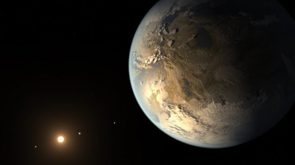
Studi Baru Bertanya: Jika Bumi Adalah Planet Eksoplanet, Mungkinkah Alien Mengatakan Itu Memiliki Kehidupan?
Studi Baru Bertanya: Jika Bumi Adalah Planet Eksoplanet, Mungkinkah Alien Mengatakan Itu Memiliki Kehidupan? – Bagaimana Bumi tampak bagi para astronom alien? Apa yang akan dikatakan pengamatan mereka tentang Bumi jika mereka mencari tanda-tanda kelayakhunian seperti kita di langit? Ini adalah eksperimen pemikiran yang menyenangkan. Studi Baru Bertanya: Jika Bumi Adalah Planet Eksoplanet, Mungkinkah Alien […]

Kode Genetik Delapan Huruf Mengisyaratkan Bagaimana Kehidupan Alien Dapat Berevolusi
Kode Genetik Delapan Huruf Mengisyaratkan Bagaimana Kehidupan Alien Dapat Berevolusi – Para peneliti telah menciptakan kode genetik ‘alien’ yang terbuat dari delapan basa, bukan empat basa biasa. Alfabet genetik yang diperluas menunjukkan bagaimana kehidupan dapat muncul jika organisme tidak pernah mengembangkan protein tetapi mengandalkan RNA sebagai pekerja keras biomolekuler mereka. Kehidupan di Bumi dibangun di […]
Apa Yang Terjadi Selanjutnya Jika Kita Menemukan Bukti Alien Luar Angkasa?
Apa Yang Terjadi Selanjutnya Jika Kita Menemukan Bukti Alien Luar Angkasa? – Pertama muncul saran bahwa ” megastruktur alien ” telah diamati di sekitar KIC 8462852, alias Tabby’s Star. Beberapa bulan kemudian, orang-orang berbicara tentang sinyal yang terlihat oleh teleskop Rusia bahwa beberapa pemikiran dipancarkan dari lingkungan sepupu bintang matahari. Apa Yang Terjadi Selanjutnya Jika […]

Apa Saja Yang Harus Dilakukan Saat Alien Muncul
Apa Saja Yang Harus Dilakukan Saat Alien Muncul – Saat Anda berada di alam liar yang belum dijelajahi, sebaiknya Anda diam, karena Anda tidak pernah tahu apakah ada predator berbahaya yang mengintai. Sayangnya, Bumi belum mengikuti prinsip peringatan ini sejauh ini: kita telah menyiarkan gelombang radio ke luar angkasa selama lebih dari satu abad. Apa […]

Apa yang Harus Kita Lakukan Jika Makhluk Luar Angkasa Muncul?
Apa yang Harus Kita Lakukan jika Makhluk Luar Angkasa Muncul? – Sulit untuk mengatakannya pada saat ini, tetapi langkah pertama yang penting adalah menentukan apakah mereka ada sehingga kedatangan di masa mendatang tidak akan mengejutkan. Apa yang Harus Kita Lakukan Jika Makhluk Luar Angkasa Muncul? alienscalpel – Saat Anda berada di alam liar yang belum […]
Audiensi Yang Ada Di Publik Pertama Pada Kongres Tentang Kemunculan UFO Dalam 50 Tahun
Audiensi Yang Ada Di Publik Pertama Pada Kongres Tentang Kemunculan UFO Dalam 50 Tahun – Hanya sedikit yang menangkap imajinasi masyarakat umum, seperti UFO dan saran fiksi ilmiah bahwa alien mungkin sedang berlibur di planet kecil kita yang sederhana. Dan pada hari Selasa, 17 Mei, Subkomite Dewan Perwakilan Rakyat AS untuk Kontraterorisme, Kontraintelijen, dan Kontraintelijen […]
Meninjau Kembali Kasus Bukit Terkenal di Era (Lainnya) Berita UFO dan Rahasia Pemerintah
Meninjau Kembali Kasus Bukit Terkenal di Era (Lainnya) Berita UFO dan Rahasia Pemerintah – “Skeptisisme adalah hal yang sehat, terutama ketika Anda terlibat dengan piring berputar yang menentang hukum aerodinamika,” tulis John G. Fuller dalam entri “Trade Winds” pada 2 Oktober 1965, kolom regulernya untuk The Saturday Review. Meninjau Kembali Kasus Bukit Terkenal di Era […]
Kedengarannya Aneh Tapi Wanita Ini Sangat Takut Pada Alien Setelah ‘sembilan penampakan UFO’
Kedengarannya Aneh Tapi Wanita Ini Sangat Takut Pada Alien Setelah ‘sembilan penampakan UFO’ – Apakah Anda percaya pada alien? Apakah menurut Anda kehidupan, yang tidak berasal dari Bumi, dapat terjadi di luar planet biru? Yah, beberapa orang melakukannya! Kadang-kadang orang telah datang dengan teori-teori keterlaluan terkait dengan apa yang disebut pertemuan mereka dengan kehidupan di […]

Dokumen AS Yang Dideklasifikasi Mengungkapkan Rencana Untuk Membuat Nuklir di Bulan
Dokumen AS Yang Dideklasifikasi Mengungkapkan Rencana Untuk Membuat Nuklir di Bulan – Serangkaian dokumen dari Advanced Aerospace Threat Identification Program (AATIP) pemerintah AS mengungkapkan bahwa badan yang sekarang sudah tidak berfungsi itu memiliki rencana untuk menguji teknologi canggih di Bulan, yang mencakup jubah tembus pandang, dan perangkat antigravitasi, lubang cacing yang dapat dilalui, dan terowongan […]
4 Tanda Teknologi Alien Ini Bisa Membawa Kita ke Kehidupan Di Luar Bumi
4 Tanda Teknologi Alien Ini Bisa Membawa Kita ke Kehidupan Di Luar Bumi – Proyek Galileo adalah misi baru yang akan memburu Tata Surya kita dan sekitarnya untuk mencari sisa-sisa peradaban asing. 4 Tanda Teknologi Alien Ini Bisa Membawa Kita ke Kehidupan Di Luar Bumi alienscalpel – Baik itu probe alien potensial – seperti ‘Oumuamua […]

Mengingat Sumber Daya Yang Tak Ada Habisnya, Tucker Carlson Memusatkan Perhatian Pada UFO
Mengingat Sumber Daya Yang Tak Ada Habisnya, Tucker Carlson Memusatkan Perhatian Pada UFO – Tucker Carlson dan timnya berkecimpung dalam bisnis televisi, jadi tidak mengherankan bahwa salah satu trailer untuk musim kedua Mengingat Sumber Daya Yang Tak Ada Habisnya, Tucker Carlson Memusatkan Perhatian Pada UFO alienscalpel – “Tucker Carlson Originals” serial dokumenter berdurasi pendek yang […]
Bagaimana Ilmuwan Bisa Memberitahu Dunia Jika Mereka Menemukan Kehidupan Alien
Bagaimana Ilmuwan Bisa Memberitahu Dunia Jika Mereka Menemukan Kehidupan Alien – Relatif segera, beberapa ahli astrobiologi terkemuka mengatakan, kemungkinan besar kita akan menemukan bukti kuat untuk kehidupan di luar bumi atau membuang kemungkinan keberadaannya ke tepi kosmos yang terus menyusut di luar jangkauan pengamatan kita yang berkembang pesat. Bagaimana Ilmuwan Bisa Memberitahu Dunia Jika Mereka […]
Untungnya Bagi Orang Percaya UFO, Laporan Resmi Meninggalkan Banyak Imajinasi
Untungnya Bagi Orang Percaya UFO, Laporan Resmi Meninggalkan Banyak Imajinasi – Harry Reid bukan lagi penguasa Senat AS, tetapi ia tetap ahli dalam meremehkan. Ketika saya memintanya untuk menjelaskan laporan resmi pemerintah yang baru-baru ini dirilis yang mengakui kebingungannya tentang lebih dari 140 penampakan benda terbang tak dikenal, dia tetap menjadi orang yang tidak banyak […]

Apakah UFO itu nyata? Mengapa semua orang membicarakannya dengan lebih serius sekarang
Apakah UFO itu nyata? Mengapa semua orang membicarakannya dengan lebih serius sekarang – Pada tahun 2007, senator Amerika Serikat Harry Reid mengungkapkan rasa ingin tahunya terhadap beberapa laporan UFO yang datang dari angkatan bersenjata. Pentagon kemudian menyelidiki ini, dan membentuk Satuan Tugas Fenomena Udara Tak Dikenal (UAPTF). Apakah UFO itu nyata? Mengapa semua orang membicarakannya […]

Jika UFO adalah alien, Obama Berharap Umat Manusia Akan Menemukan Landasan ‘Bersama’
Jika UFO adalah alien, Obama Berharap Umat Manusia Akan Menemukan Landasan ‘Bersama’ – Mantan presiden AS Barack Obama tidak mengaku mengetahui asal usul benda terbang tak dikenal yang ditemukan oleh personel militer Amerika tetapi jika mereka berasal dari planet lain, dia ingin berpikir bahwa pengetahuan akan menyatukan umat manusia, daripada merobeknya. kita terpisah. Obama membuka […]

Pencarian Tentang Keberadaan Alien
Pencarian Tentang Keberadaan Alien – Keinginan untuk mengetahui tempat kita di alam semesta adalah kerinduan inti manusia, dan orang-orang telah merenungkan pertanyaan itu selama ribuan tahun. Memang, ratusan tahun sebelum kelahiran Kristus, para filsuf Yunani seperti Anaximander dan Epicurus berspekulasi bahwa kosmos dipenuhi dengan planet-planet, banyak di antaranya mungkin mendukung kehidupan. Pencarian Tentang Keberadaan Alien […]
5 Kali UFO dan Alien (mungkin) terlihat di New Mexico
5 Kali UFO dan Alien (mungkin) terlihat di New Mexico – Jika ada sesuatu yang lebih dekat hubungannya dengan New Mexico daripada Hatch green chile, itu adalah alien dan UFO. Tanyakan kepada siapa pun apa yang mereka ketahui tentang penampakan makhluk luar angkasa dan kemungkinan besar mereka akan melontarkan informasi tentang Roswell . Jika wajah […]
Keyakinan dan opini tentang adanya kehidupan di luar bumi
Keyakinan dan opini tentang adanya kehidupan di luar bumi – Benda Terbang Tak Dikenal (juga disebut UFO) biasanya terkait dengan kepercayaan magis yang menerima keberadaan makhluk luar angkasa dan penculikan alien. Oleh karena itu, pengalaman UFO menggambarkan kontak dengan UFO, makhluk luar angkasa, kunjungan alien terselubung, dan penculikan. Keyakinan dan opini tentang adanya kehidupan di […]